Airflow, humidity, temperature and contamination requirements define the HVAC boundary.
Electronics cleanroom integrated-energy audit example
Clean dry air, process cooling, exhaust and cleanroom HVAC diagnosed as one precision manufacturing utility system.
This case maps precision assembly or semiconductor-support operation into CDA, tool cooling, cleanroom airflow, exhaust/make-up air, humidity control and electrical demand.
- CDA quality, pressure and dew point are treated as production constraints.
- Process cooling is separated from cleanroom comfort cooling.
- Exhaust and make-up air are reported as conditioning load, not only fan energy.
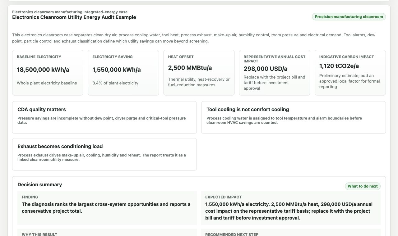
Actual diagnosis output
CDA, process cooling, exhaust and cleanroom HVAC separated before totals.
The report connects quantified savings to tool conditions, air quality and the next measurements required.
Utility boundary first
Electronics cleanrooms combine air quality, cooling and high electrical density.
The report starts by separating cleanroom airflow, CDA, process cooling and exhaust/make-up air because each one has a different engineering constraint.
CDA pressure, dew point and quality determine compressor and dryer opportunities.
Tool cooling and chilled-water temperature are separated from comfort cooling.
Process exhaust becomes fan energy and outdoor-air conditioning load.
Tool, UPS and support loads can dominate demand profile.
Air quality and tool temperature limits cap savings measures.
Diagnosis result structure
What the electronics workflow produces.
The report shows CDA, HVAC, process cooling, exhaust, humidity and demand sections with confidence labels and data needed for stronger quantification.
Measure groupWhy it mattersEnergy boundaryData to improve confidence
CDA pressure, dryer and leakage review
CDA is often high-value compressed air with strict quality needs.
Compressor and dryer kWh.
CDA flow, pressure, dew point and compressor trend.
Process cooling reset
Cooling temperature affects tool stability and chiller energy.
Process chiller and pump kWh.
Tool cooling trend, supply/return temperature and load.
Exhaust and make-up air balance
Exhaust flow creates both fan power and conditioning load.
Fan, cooling and heating energy.
Exhaust flow, make-up airflow and schedule.
Cleanroom fan/static pressure review
Fan energy is continuous and interacts with cooling load.
Fan kWh with fan heat counted once.
Airflow, static pressure, filter loading and room schedule.
Quantification package
What must be measured before this becomes a decision-ready electronics report.
The report quantifies CDA, process cooling, cleanroom HVAC, exhaust and demand only after production-quality boundaries and utility meters are connected.
Calculation layerRequired site dataMethod outputConfidence and M&V
CDA baseline
CDA flow, pressure, dew point, dryer type, compressor kW and operating schedule.
Specific power, dryer penalty and pressure/leakage opportunity.
Measured result with flow and power trend; engineering estimate with compressor trend and dew point.
Process cooling and exhaust
Tool cooling load, chilled-water supply/return, exhaust flow, make-up air and humidity target.
Process cooling kWh, make-up air conditioning load and fan kWh.
M&V uses tool cooling trend, AHU/exhaust status and cleanroom condition compliance.
Overlap control
Cleanroom fan heat, cooling load, humidity control and exhaust make-up air assigned to one AHU/tool boundary.
CDA, process cooling and HVAC measures are summed only after shared load is removed.
Yield, tool temperature and cleanroom condition records define implementation limits.
Reference-backed method
Public method references behind this electronics cleanroom case.
These references are used as method context for audit structure, system boundaries, evidence quality and M&V planning. They do not confirm site savings; the workflow still requires site data before investment use.
Reference familyHow it supports this case
ISO 50002 / ISO 50001
Energy-audit structure, baseline ownership and report evidence labels.
ISO 14644 cleanroom context
Controlled-environment and particle-control boundary for clean manufacturing.
DOE compressed-air and ASHRAE HVAC context
CDA pressure/dryer purge plus exhaust, make-up air, humidity and reheat interactions.
Before running the workflow
What an electronics cleanroom user can judge before running the workflow.
This page shows the industry-specific signals used in the detailed diagnosis report, so a visitor can judge relevance before entering site data.
Visible signalWhat it tells the user
Process signal
CDA, PCW, process exhaust and room HVAC are four separate utility boundaries.
Energy signal
Tool cooling and exhaust/make-up air are treated separately from comfort cooling.
Boundary signal
Tool alarms, dew point, room pressure and exhaust classification gate savings.
Use this electronics cleanroom case as a utility diagnostic intake.
Start from CDA, process cooling, cleanroom HVAC and exhaust data, then unlock the full report when the result is useful. Use the example diagnosis to inspect the method, or start a clean diagnosis with your own facility data.