IT power defines the reference load used to interpret facility overhead.
Data center cooling integrated-energy audit example
IT load, cooling overhead, UPS losses and airflow diagnosed as one data center energy system.
This case starts from the IT load and builds outward: PUE, cooling plant, CRAH/CRAC fans, economizer opportunity, UPS efficiency, heat rejection, redundancy and electrical demand.
- Uses IT load as the reference boundary before evaluating cooling and power overhead.
- Separates cooling kWh, fan kWh, UPS losses and demand charge.
- Keeps all measures inside redundancy and IT environmental requirements.
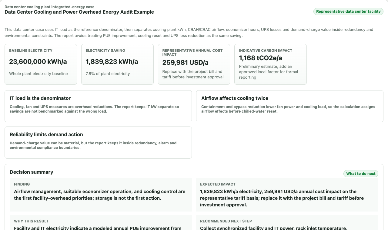
Actual diagnosis output
IT load, cooling, airflow and UPS losses kept inside the reliability boundary.
The report distinguishes quantified opportunities from the measurements and redundancy checks still required.
Load boundary first
Data center energy analysis starts with IT load, not the chiller room.
Cooling improvements, UPS losses and airflow changes only make sense after the IT load, redundancy level and environmental envelope are clear.
Chillers, pumps, towers, dry coolers or direct expansion systems remove IT heat.
Containment, bypass, recirculation and fan control determine how efficiently cold air reaches IT equipment.
Climate, temperature limits and redundancy decide when compressor energy can be reduced.
UPS loading and efficiency create electrical loss before cooling interaction is considered.
Peak charge and demand response are reviewed separately from kWh savings and bounded by SLA/redundancy requirements.
Diagnosis result structure
What the data center workflow produces.
The report separates IT reference load, cooling overhead, fan energy, UPS losses, economizer potential and demand-charge impact before adding project value.
Measure groupWhy it mattersEnergy boundaryData to improve confidence
Airflow containment and bypass reduction
Bypass air and recirculation raise cooling and fan demand.
Fan/cooling kWh with overlap control.
Temperature map, rack airflow, containment condition and fan speed.
Cooling temperature and plant reset
Chilled-water or supply-air temperatures affect compressor lift and equipment limits.
Cooling plant electricity.
Supply/return temperatures, chiller kW and IT inlet temperature.
Economizer opportunity
Ambient conditions can reduce compressor operation when controls and redundancy allow.
Cooling kWh reduction.
Weather bin data, economizer status and temperature envelope.
UPS loading and efficiency review
Part-load UPS operation can create avoidable electrical loss.
Electrical loss, separated from cooling savings.
UPS load, efficiency curve and power distribution data.
Demand management
Peak power costs may be material even when kWh changes are modest.
Demand charge separately reported.
Utility interval data, redundancy state and operating constraints.
Evidence basis
Public references support the data center energy boundary.
Supports IT, cooling, power delivery and environmental-control categories.
Open public referenceSupports data center electricity-demand context and grid relevance.
Open public referenceThe workflow is designed for IT load, facility power, cooling plant trend, UPS data and temperature maps.
Quantification package
What must be measured before this becomes a decision-ready data center report.
The report quantifies cooling and power overhead only after IT load, facility power and reliability constraints are defined. The case defines the calculation basis before any measure is treated as decision-ready.
Calculation layerRequired site dataMethod outputConfidence and M&V
IT and facility energy baseline
IT kW, total facility kW, PUE trend, UPS loading, cooling plant kW and interval demand.
Cooling overhead, UPS loss and demand-charge boundary separated from IT growth.
Measured result with interval meters; screening estimate with monthly energy and IT-load snapshot.
Airflow and cooling reset
Supply/return air temperatures, bypass/recirculation observations, CRAH/CRAC status and chilled-water or DX cooling trend.
Cooling kWh and fan kWh opportunity inside environmental and redundancy limits.
M&V uses before/after PUE, cooling kW, inlet temperature compliance and alarm history.
Overlap control
Containment, temperature reset, economizer and UPS measures assigned to separate energy boundaries.
Cooling reduction, fan reduction, UPS loss and demand charge are not summed twice.
Reliability state and redundancy mode remain required report fields.
Reference-backed method
Public method references behind this data-center case.
These references are used as method context for audit structure, system boundaries, evidence quality and M&V planning. They do not confirm site savings; the workflow still requires site data before investment use.
Reference familyHow it supports this case
ISO 50002 / ISO 50001
Audit structure, evidence quality and reportable energy-performance findings.
ASHRAE TC 9.9 data-center thermal resources
Rack inlet conditions, environmental envelope and cooling-management context.
DOE data-center energy resources
Facility energy, cooling, UPS/electrical overhead and PUE-style boundary review.
Before running the workflow
What a data-center user can judge before running the workflow.
This page shows the industry-specific signals used in the detailed diagnosis report, so a visitor can judge relevance before entering site data.
Visible signalWhat it tells the user
Process signal
IT load is the denominator before cooling, CRAH, economizer, UPS or demand measures.
Energy signal
Airflow containment, cooling reset, economizer and UPS losses are separate streams.
Boundary signal
Rack inlet temperature band, alarm history and redundancy mode gate savings.
Use this data center case as a cooling and power-overhead screen.
Start from the data center workflow, then replace the sample method inputs with IT load, cooling, UPS and interval power data. Use the example diagnosis to inspect the method, or start a clean diagnosis with your own facility data.